Red Phase
Showing 1–24 of 31 results
-

100A 3 PHASE METER TESTER: MODEL 689B
The Model 689B meter tester uses a Digital Signal Processor
and a display processor to measure and calculate meter
errors to 0.03% or 0.1% accuracy.The Model 689B has a 3 phase switch mode current source.
For testing direct connected meters to 100A there are 6 large
6mm sockets on the front panel. Testing C.T. meters to 10A is
done using the multi pin “CURRENT” socket on the front panel.The model 3028 clip on C.T. clamps have basic phase and
ratio accuracy of 0.2%, which allows accurate testing of direct
connected polyphase and single phase meters without the
need to disconnect the meter wiring or interrupting supply to the
customer.Up to 1000 test records can be stored for review or later
downloading to a USB flash drive.
The chassis of the 689B is fitted in a rugged transit case using rubber mounts to protect it against
rough handling in the field. There is a carry handle on top and both ends of the case. -

100VA PHANTOM LOADS:MODEL 467B-30
This 3 phase phantom load is used for energising CT or Direct
connected Energy meters during commissioning or routine testing.
The 467B-30 can deliver over 100VA per phase at 100Amps / 1V.“Variacs” are used to adjust the current injection amplitude from zero
to full scale. Shrouded safety plugs and sockets are used to connect
the cables to the front panel. The input required is 240V/415V 3 phase,
4 wire and this is protected with a 3 pole circuit breaker. -

10A 3 PHASE PHANTOM LOAD: MODEL 462F
The Model 462F is designed for use with any field test set for testing polyphase CT meters.
It can be powered from the metering test block, and will test nominal 240V, 3 phase, 4 wire star connected L.V. meters or nominal 63.5V star connected H.V. meters.
It can also test nominal 110V, 3 phase, 3 wire delta connected meters.
This phantom load can be used with the Red Phase Instruments Model 679 and 679B polyphase meter testers, or any other meter tester.The 3 current outputs are variable from 0 to 100% in 1A and 10 A ranges in coarse (10%) and fine (1%) increments. Phase angle/power factor settings are available from 60º LEAD to 90º LAG in 15º increments
-

200VA Current Injection Unit: MODEL 4061
Portable current injection system designed to simulate system fault
currents and their effects on electrical and utility infrastructure
such as:
– small to medium substations
– telecom towers
– transmission pylons
– wind turbines
– rail yards and their subs
– and other disconnected earthing systems…Features:
– pure sinusoid injection current with frequency selection between
40Hz to 70Hz, in increments if 1Hz.
– on board web server including 3G/4G modem for remote status
monitoring and injection control via mobile phone.
– on board GPS for cable-less phase synchronization with Red
Phase 4031 and 4025E tuneable multimeters.
– 7 injection ranges to choose from:
160V / 1.25A on a 128 Ohm tap
120V / 1.67A on a 72 Ohm tap
80V / 2.5A on a 32 Ohm tap
60V / 3.33A on a 18 Ohm tap
40V / 5.0A on a 8 Ohm tap
30V / 6.67A on a 4.5 Ohm tap
20V / 10.0A on a 2 Ohm tap
– comes with trolley handle and wheels for ease of transport
– only 20 Kg.Please download the Preliminary data sheet for more information.
-

20A 3 PHASE PHANTOM LOAD:MODEL 473
Simple and easy to use 3 phase phantom load used in pre or post commissioning of metering and / or measurement products.
Easy way to determine correct installation and phasing of
equipment.
Supplied cable accessory is 4 metres long and is capable of providing 7.5 to 8 Amps of load current.
With shorter and thicker gauge cabling the 473 is capable of providing up to 20 Amps of load current per phase. -

2kVA Current Injection Unit: MODEL 4046
The Model 4046 is a frequency adjustable switch mode
current injection source that is used to drive the primary of
a multi tapped coupling transformer to induce variable
voltage and current magnitudes into an earth or passive
load loop at maximum power continuously if required.Typically the earth test loop / circuit consists of the earth grid
under test connected to a remote earth grid through an earth
path in the ground. To complete the loop, a return connecting
path isolated from earth, usually an ‘out of service’ feeder or
separate injection line is also used. The test current is driven
around the loop by the secondary winding of the Model 4047C
Coupling Transformer which is inserted into the loop.Frequencies from 40Hz to 70Hz can be selectively generated
by the 4046 to avoid interference with background line
frequency. Voltage drops generated by the injected current
around the earth loop are measured with a frequency
selective multimeter fixed to the current injection test
frequency.Measureable results over the test landscape can be profiled with the 4025E or 4031 frequency selective
multimeter. Both the 4025E or 4031 and the 4046 Injection system have a GPS function which is used
for position location and phase synchronization which frees up the need for phase reference cabling
during current split measurements and also provides relative positioning information so that the operator
may choose the best line of potential measurement during EPR tests to avoid mutual coupling/induction. -

3 PHASE REFERENCE STANDARD: MODEL 691
The Model 691 is a moderately priced 3 phase reference standard.
It is packaged in a 19” style bench-top case with all connections on the front panel for use in meter test benches.The software enables meter testing with all the common type of real and reactive kWh meters, both disc and electronic types.
The LCD readout shows all the parameters in the test circuit as well as meter test results.
-

8kVA Current Injection Unit: MODEL 4041
The Model 4041 is the largest of our switch mode current injection sources used for injection based testing.
This 3 phase unit works on the identical principle of operation
as our 2kVA system, however the 4041 in conjunction with
the 4042 coupling transformer have been specifically
designed to perform current injection tasks over very long
haul and demanding environments continuously at maximum
power.With our 4025E or 4031 frequency selective multimeters,
terrestrial voltage profiling is made easy with GPS positional
information available on both the 4041 and 4025E/4031 units.Another advantage of this is the ability for the two units to
synchronize phase readings, thus reducing the cabling
required when performing current split or branch
measurements and it also provides relative positioning
information so that the operator may choose the best line
of potential measurement during EPR tests to avoid
mutual coupling or induction. -

Continuity Tester: MODEL ECT-4
The ECT-4 is a 4 wire Kelvin micro-ohm meter used to check the
electrical quality of metallic structures and their connection integrity
to other bonded structures in grids and electrical systems such as a
sub-station or transmission station.A custom back pack carry case houses a power source which injects
discrete levels of current at 1, 2 or 3 Amps directly between two points
in the grid connected network.The ECT-4 and it’s extension reel accessories allow this test to be
performed over small or large distances using a single Earth reference.The ECT-4 has filtering for excellent 50Hz and 60Hz rejection and also
features 5 current direction modes to further mitigate DC offset and
interference:The 5 current direction modes are:
– Forward
– Reverse
– Pulsed Forward – pulse duration can be changed in 1 second increments
– Pulsed Reverse – pulse duration can be changed in 1 second increments
– Pulsed Bipolar with or without dead time – dead time duration can be changed in 1 second incrementsMeasurements are taken with a moulded hand probe which includes twisting retractable stainless steel
pins used to make the surface connection with a bonded metallic object.The hand probe has a 5cm backlit LCD which displays the results of the bond down to a 10uΩ resolution.
The injection mode described above and current range can also be selected on the hand probe via three
tactile push buttons.The ECT-4 runs off a separate battery, also carried in the back pack, giving the operator single handed
operation and superior mobility while performing continuity tests for over 5 hours.The ECT-4 comes with all accessories necessary to begin testing straight out of the box.
Please download the data sheet for more information.
-

COUPLING TRANSFORMER: MODEL 4042/3
Model 4042 is our largest coupling transformer, with eight
secondary taps rated to 8kVA.
The 8 taps on the 4042 allows the user to adjust the injection
voltage and current to a desired value via individual tap
settings whose impedance ranges from 1 to 80 Ohms.When the correct tap is chosen and the tap menu settings
on the injection unit is set to the same value, the amplifier
will see a large reflected load and will deliver maximum
power through this tap to drive current around the earth loop.As with the lower power units, the primary of the coupling
transformer is driven by the Model 4041 injection unit up to
a nominal 320V. The various secondary taps on the 4042
translate the input from the injection unit to an output
voltage range from 90V to 800V.
Each tap on the coupling transformer is connected to a
feedback circuit which constantly senses the earth loop’s voltage and current / load.
The injection unit uses this data to maintain a constant injection current at maximum power.The 4042/3 also comes with cooling fans and a thermal cut out switch for safe operation.
-

COUPLING TRANSFORMER: MODEL 4047/C
The 4047/C is a 2kVA rated coupling transformer with eight
individual tap settings covering an impedance range from
5 to 400 Ohms.
Used in conjunction with the Model 4046 the tap selection must also be reflected in the tap menu settings of the Injection Unit which also drives the coupling transformer.When the correct tap is chosen the Amplifier will see a large reflected load and it will be able to deliver maximum power.
The unit also comes with all necessary current, voltage and
load sensing circuitry along with 2 fans and a thermal cut-out switch for safe operation over wide temperatures. -

CT & PT Tester: Model 590J-V2
Performing field test measurements of Current and Potential
Transformers has been made far simpler with the Model 590J-V2.This full featured product combines all of the metering CT test
abilities of the popular 590G-V2 model with the additional advantage of also being able to perform both protection CT
excitation tests as well as burden based inductive PT tests.The 590J-V2 eliminates the need for additional bulky accessories
usually required to perform various tests on different types of
equipment, saving the operator valuable time and money.Light weight and portable, the 590J-V2 is housed in a ruggedized
plastic case and is supplied with the necessary test cables and
attachment accessories. It is further packaged in a foam lined
transit case for safe transport.It features the following offline test capabilities:
– Burden based CT and PT ratio and phase error measurements
to an accuracy of 0.02%
– Excitation measurements of Protection Class CTs
– Optional Live CT test capability with 590F accessory
– CT and PT secondary winding resistance, PT primary included
– CT 1.6 kHz Admittance test
– Simulated Full Load inductive PT testing on up to 2 windings with
or without Junction box
– CT and PT Burden test
– CT and PT polarity check
– Batch testing of metering CTs
– No name plate CT Class Estimation
– Record download to USB Flash or optionally via Bluetooth to an Android tablet or phone.
This full featured CT and PT test instrument lowers testing costs by being simple, fool-proof and fast.
It’s capabilities allow utility personnel and test technicians to pursue the very important task of testing field
based instrument transformers for measurement losses, faults or tampering. -

CT Tester: Model 590G-V2
Since 1999, Red Phase Instruments has led the way in the manufacture of portable CT error testing equipment.
Our portable analysis method has allowed utilities around the world to test their metering CTs easier and faster than using bulky traditional methods without jeopardizing accuracy.Following feedback from our users, our Model 590G-V2 is the latest version of this successful and well proven CT error tester.
The 590G-V2 has all the features and advantages of the previous models with additional testing features, better accuracy and smaller size and weight.
In a world where cost control is gaining importance, this CT tester not only lowers testing costs by being simple, fool-proof and fast. It also allows utilities to pursue the very important (yet at many times forgotten) task of testing installed CTs for detecting tampering, and minimizing losses due to faulty CTs.
Test capabilities:
Offline
CT Ratio and phase error measurements to an accuracy of 0.02%.
CT 1.6 kHz Admittance test.
Graphical display or plot of the CT’s excitation curve.
Burden test.
Measures CT winding resistance.
Performs a CT polarity check.
PT full load simulated tests (with 590D-1 accessory)
Live
Live CT testing (with 590F accessory) -

CVT Tester: Model 590K
True burden based CVT analysis done portably!!
Features include:
Ability to test for ratio errors at up to 500VA burden.
Selectable Power Factor.
Ratio error accuracy to 0.05%.
Four selectable CVT test point standards to choose from.
Tests CVT rated to 500kV with up to 3 secondary windings.
Truly portable ~ 20kg.
Please note:
This is not a simple ratio / nameplate comparison tester.The R & D that has gone into developing this instrument is second to none.
Over 60 CVT’s from over 12 manufacturers have been carefully characterized under lab and field conditions to create a complex software
model that is able to measure a known CVT down to a 0.05% or better ratio error and even an
unknown CVT to only a 0.25% error under real load conditions.Under test conditions the 590K takes a number of measurements and characterizes the CVT.
It then calculates the performance of the CVT under different loads and applied voltage conditions to suit
any of the four common test types used on a CVT.
If other test points are required, Red Phase Instruments is able to modify these points to suit any
regulation.So when compared to traditional methods the 590K stands out as the only real portable alternative for
real load ratio assessment over a wide VA range and flexible Power Factor settings.The CVT tester uses a combination of a Digital Signal Processor and a PC104 mini computer to provide
a powerful and yet easy use instrument running on a Windows XP operating system.
A large colour display on the front panel presents a large amount of easy to follow information. -

Frequency Selective Multimeter: MODEL 4025E
The 4025E is the latest revision in our 4025 series of frequency selective
multi-meters. It maintains all of the features of the previous models for
measuring the I/V magnitudes and phase of signals induced into an earth
loop via high power current injection.The 4025E has been designed with better step resolution allowing for
measurement of injection frequencies to 0.1 Hz off main line frequency
without interference.
Designed to be used with our new GPS based injection products, it takes
full advantage of the GPS features to synchronize with the injection system and provide the operator with cable free current phase referencing and a visual display of the operator’s relative position to the other injection points
during large earth system potential measurements.The 4025E runs off an internal rechargeable battery with a
7 to 8 hour field time before requiring re-charge. -

Frequency Selective Multimeter: MODEL 4031
When performing earthing/grounding system tests it is essential to filter out the predominant 50 or 60Hz currents that are often present in a typical test situation.
This is done by injecting at frequencies other than 50 or 60Hz
and making sure that the instrument which detects voltages and
currents around the loop is tightly tuned to the same frequency.The 4031 is a hand held frequency selective ammeter and voltmeter used to measure the I/V magnitudes and
phase of signals induced into an earth loop via a
high power current injection system such as the
Model 4041 and 4046.
The voltmeter part of the 4031 allows, fall of potential and step & touch voltages
to be measured easily and accurately, which is important for the safety of both
the general public and utility personnel.
In earth loops, measurements are made of voltage, current and phase angles
enabling the impedance of the circuit to be calculated by the software.The 4031 runs off an internal rechargeable Li-ion battery which lasts 5 to 6 hours.
The 4031 comes in two variations. A Rogowski coil type or a LEM~flex RR3020 AC current probe type, but not both. The Rogowski coil and LEM current probe are available as optional accessories.
The 4031 also has an on board GPS feature which is used for cable-less phase synchronization when performing current branch measurements.
The 4031 Multimeter operates in the 40 – 69 Hz range, rejecting both 50 Hz or 60 Hz power frequencies.
The high quality of the Multimeter’s filters allows it to be used at frequency resolutions to 0.1Hz deviation
from the baseline power frequency with no interference. -

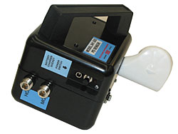
GIS PD TESTER: MODEL 840U AND 841
To help in maintaining GIS ( gas insulated switchgear ) equipment we developed the Model 840 GIS tester which is designed to take the output signal from a Model 841 GIS sensor. The signal is interpreted by a dedicated microprocessor unit in the 840U which in turn sends digital data to the laptop PC. In the laptop PC the digital data is used to construct graphical representations of the PD activity.
The portable Model 841 is fitted with a high frequency amplifier matched to the typical PD signature of GIS equipment. It has a rechargeable Li-On battery for extended field use, and is connected to the 840U with a coaxial test cable. There is a swivel attachment on the 841 so it can be used on the end of a hot stick when required.
-

HANDHELD CT BURDEN TESTER: MODEL 704
This small battery powered tester is ideal for carrying out
quick burden checks in CT metering and protection circuits.The clipon CT (pictured) is connected to the CT secondary wiring and the crocodile clips attached to the CT terminals.
The instrument calculates the burden as the ratio of voltage over current.The burden measurement accuracy is typically 1% at 5A and 5V, and decreases to 5% at 0.01A and 0.01V.
-

Lightning Impedance Tester: MODEL 4051
The 4051 lightning impulse impedance tester is used to inject a simulated
lightning impulse signal at up to 30 Amps between two electrodes such as
a Pylon footing and a remote test electrode.A measurement of the ground impedance between between the two is
determined automatically and if the operator so chooses they may also
perform a further test to determine how the same impulse can affect the
potential of a nearby metallic object within the impulse path.Two tests are available:
– Direct Impedance test
– Electrode Impedance testThese tests may be performed with one or both of the impulse wave shapes below:
8 / 20uS
10 / 350uS
More impulse shapes are available upon request, (contact RPI), however the two outlined above
have been found to give the most practical and consistently reliable results. -

Live CT Tester: MODEL 505B
In high revenue areas such as universities, shopping malls
and business centres, taking CT’s offline for testing is not
an option, so a reliable live CT test alternative is required.Live CT testing using admittance…
A component of a good CT’s characteristic performance is
a low admittance value. This admittance value can be measured while in-circuit using the 505B (pictured).
The 505B is placed in series with an in-circuit CT and it
superimposes a small 1.6kHz signal onto the live 50 or 60Hz
secondary metering circuit.
A filter on board the 505B extracts the 1.6kHz admittance
reading and from this a quick determination is made on the
CT’s general health.
Admittance testing only adds an extra 10 minutes to a polyphase
meter test and is quickly becoming part of a routine test requirement
for some utilities.The 505B can perform the following measurements:
Voltage and current at 50 or 60Hz.
1.6kHz admittance test on a CT secondary.
1.6kHz admittance test on a CT secondary plus the complete metering loop.
VA burden of the metering loop downstream from the test block, or at the CT secondary terminals.
VA burden of the metering loop from VT secondary terminals or at its test block.A USB interface is also provided on the front panel for downloading results data to a PC.
-

Live HV CT Tester: Model 590F
For customers who cannot be disconnected or offline when performing
metering CT tests, the 590F1 or F3 HV (High Voltage) accessory can be
added as a retrofit kit to our popular 590G and 590GV2 CT testers.The first part of the kit is the clamp on CT unit which is mounted on
the end of a hot stick. This unit has a battery powered electronic
compensation circuit for the clamp on CT (“clip on”) which greatly
improves accuracy over a wide operating range, typically 5A to 1450A.A microprocessor is also used to control the clip on compensation,
manage the internal range changing and provide communications via
a fibre optic and RS-485 interface.The fibre optic cable runs between the 590F1 and a small interface unit at the base of the hotstick.
From there the signal is transmitted through a 100M drum of RS485 cable to the 590C/G or G-V2
CT tester.
The combination of hot stick and cable has been tested to 100kV, line to ground.
The actual breakdown voltage of the hotstick and fibre optic cable is much greater than 100kV,
but for operator safety we suggest not using this test set above 100kV. However, with a longer
hotstick and suitable precautions the 590F1 or F3 unit can be used at higher voltages.The CT primary current measured by the clipon is sent via the cable to the 590G or G-V2 CT Tester
which can be up to 100M away. Extra drums can be daisy chained up to 400M in total.
The 590C/G or G-V2 unit measures the CT secondary current, 5A, 1A or lower, and then calculates the
CT ratio and phase error to an accuracy of 0.1%.For testing live LV Low Voltage or low current CTs, we have a variety of electronically compensated
clamp on CT’s, “Clip ons”. Let us know what you require and we can adapt the 590F to suit.We have two regular low to medium voltage clip ons. One is for cables carrying up to 1,000A and the other is a large jaw clip on for busbars up to 2,500A.
-

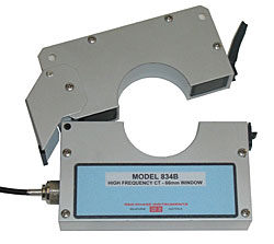
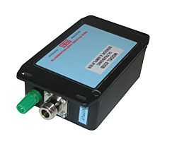
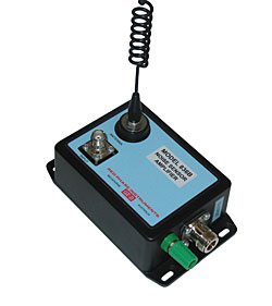
PD SENSORS: MODEL 834B, 835B, 836B
These sensors are used to amplify the very low level PD signals and transmit them via coaxial cable to the Model 831 and Model 832B units. The 834B is a split core high frequency CT with 66mm window. For transformer testing a good choice is the 835B ultrasonic sensor which has a strong magnetic base capable of gripping the steel tank of the transformer.
Rejecting spurious signals is important when performing PD tests, and for this purpose we have the 836B noise sensor. This sensor picks up and amplifies ambient electrical noise with its aerial, and the signal is then sent to the 831 or 832 so they can discard any apparent PD which occurs at the same time which may be due to noise.
-

PHASE ANGLE METER: MODEL 597C
A precision phase angle meter in 50Hz or 60Hz version, the 597C has been in production for well over 10 years. It has inputs for voltage, direct current or current via a clipon CT.
The phase angle can be measured to 0.1deg accuracy over a wide range of voltage from 10V to 500V, and from 50mA to 50A using the direct current input.
The clipon CT option gives current measurement up to 500A with slightly less accuracy.
-

PHASOR METER: MODEL 633
This complements the Model 632A, since the Model 633 reads phase angle, true rms voltage and true rms current in a circuit. This instrument is designed to demonstrate the properties of phasors and real/imaginary number notation for electrical engineering students. This instrument gives the phase displacement and magnitude of the parameter under investigation. The unit has filters to eliminate harmonic distortion affecting phase angle measurement.
The instrument has 500V and 50V voltage ranges and 10A and 1A current ranges plus a 500V range reference voltage input. Phase angle accuracy is typically 0.5º and voltage /current accuracy is 0.3% at 50 Hz, 20% distortion.